VELHEAT

Electric Duct & Air Heaters

Electric duct and air heaters place resistance-heating elements within a moving air stream.

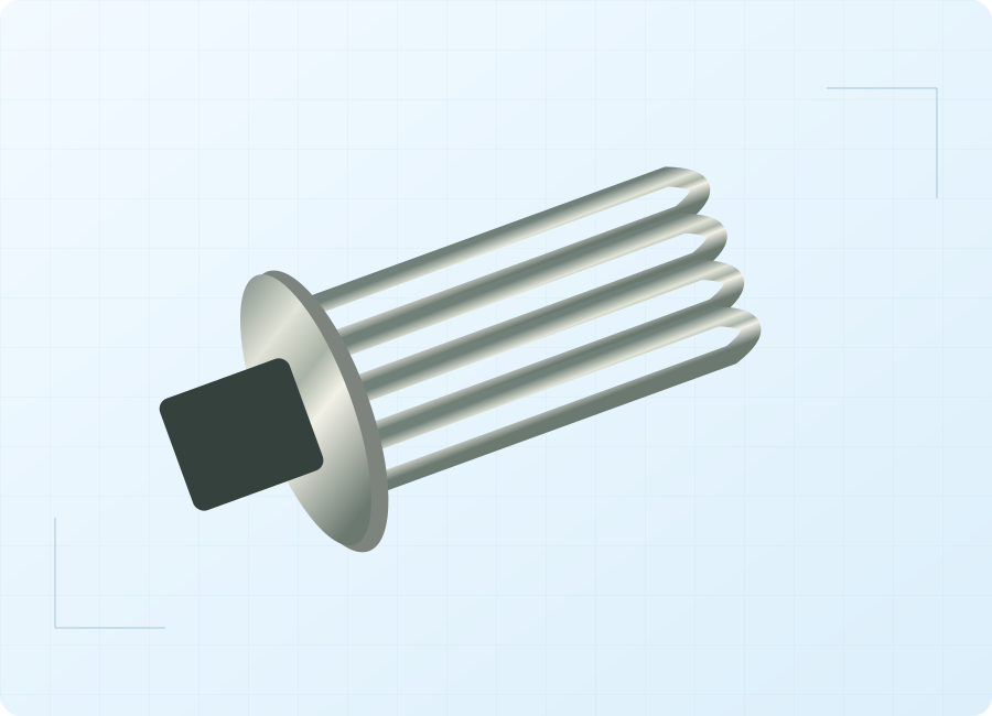
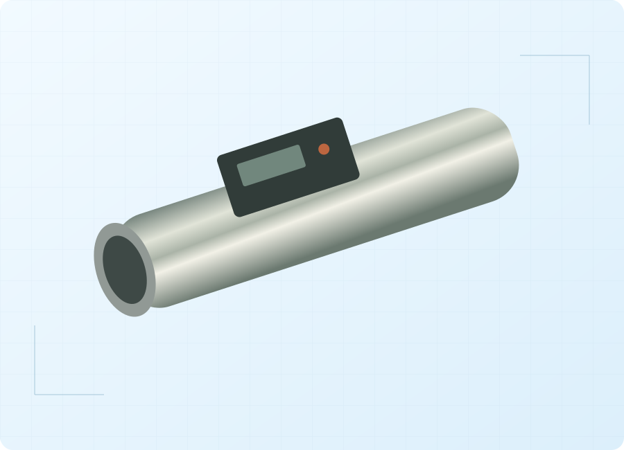
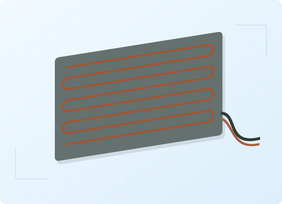
Electric Duct & Air Heaters — conceptual product-form illustration
Product-form illustration. Final construction follows the agreed specification.

About Electric Duct & Air Heaters

Electric duct and air heaters place resistance-heating elements within a moving air stream. The heated air may support building ventilation, drying or an industrial process. Heater performance depends on both total airflow and its distribution across the element bank. A duct with adequate average flow can still contain poorly swept regions. Selection therefore includes the inlet condition, duct transitions, nearby obstructions and the minimum permitted operating flow. This is an air-side product: a heater installed in an HVAC water circuit belongs to a different application and requires a different design review.

Define the minimum airflow, inlet condition and required temperature rise, then match the heater face, element arrangement and controls to the duct and operating sequence. Electrical power is only one part of that specification.

Product Configurations

Ventilation auxiliary heaters

For adding heat to an HVAC air stream. Define outside-air conditions, supply-air targets and the ventilation system's turndown range, together with the building control sequence and available electrical capacity.

Enquire about this configuration

Industrial process-air heaters

For heating air used by production equipment. Start with inlet temperature, composition and continuous duty, then review the element environment and the required temperature at the process entry.

Enquire about this configuration

Drying and reheat arrangements

For processes where air temperature is part of a moisture-management sequence. Explain the airflow route, recirculation, exhaust and material being treated so heater selection fits the whole process.

Enquire about this configuration

Air heaters for ash-handling systems

For air-heating duties associated with power-station ash handling. Clarify whether the heater sees clean upstream air or a contaminated stream; dust exposure cannot be inferred from the application name.

Enquire about this configuration
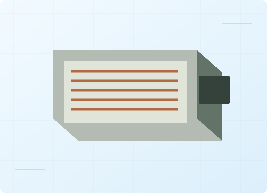
Electric Duct & Air Heaters — conceptual product-form illustration

Customize for Your Application

Element-bank layout

Discuss the distribution of elements across the useful airflow area. A larger duct dimension does not automatically mean every part of the heater receives adequate cooling air.

Mechanical interface

Use a duct drawing to review the frame, mounting position and maintenance access. Include insulation thickness and the space needed to remove the assembly without disturbing unrelated equipment.

Power regulation

Compare staged and modulated heat with the response needed by the process. The discussion should include the minimum stable load and the way the fan changes speed.

Independent protection

Define airflow proving and overtemperature protection separately from the normal temperature loop. Agree which conditions prevent energization and which faults require investigation before restarting.

Technical Information to Specify

Share these details with your inquiry. Product ratings and operating limits are confirmed for the selected configuration.

What to specifyUnit / formatSelection guidance
Air volume and minimum flowm³/hGive normal, minimum and maximum flow, plus the reference temperature and pressure for the figures.
Inlet and outlet temperatures°CSpecify the coldest inlet, hottest inlet and required outlet condition at each operating case.
Duct and heater openingmmProvide internal dimensions, airflow direction, orientation and the proposed insertion or connection arrangement.
Pressure allowancePaState available fan pressure and the permitted pressure drop across the heating assembly.
Air compositionprocess descriptionIdentify humidity, particulate loading, corrosive constituents and any flammable vapor or combustible dust.
Electrical supplyV / Hz / phaseProvide supply details and the available capacity for the required heating stages or modulation.
Control interfacesignal / sequenceDescribe temperature demand, fan status, flow proving, fault indication and the supervisory control interface.
Installation envelopemm / °CShow service access, adjacent duct fittings and the ambient condition around the terminal enclosure.
Air volume and minimum flow
m³/h

Give normal, minimum and maximum flow, plus the reference temperature and pressure for the figures.

Inlet and outlet temperatures
°C

Specify the coldest inlet, hottest inlet and required outlet condition at each operating case.

Duct and heater opening
mm

Provide internal dimensions, airflow direction, orientation and the proposed insertion or connection arrangement.

Pressure allowance
Pa

State available fan pressure and the permitted pressure drop across the heating assembly.

Air composition
process description

Identify humidity, particulate loading, corrosive constituents and any flammable vapor or combustible dust.

Electrical supply
V / Hz / phase

Provide supply details and the available capacity for the required heating stages or modulation.

Control interface
signal / sequence

Describe temperature demand, fan status, flow proving, fault indication and the supervisory control interface.

Installation envelope
mm / °C

Show service access, adjacent duct fittings and the ambient condition around the terminal enclosure.

Operating Limits to Check

  • Minimum airflow and the permitted flow profile are assembly-specific operating conditions.
  • Air-side heaters cannot be substituted for water-side HVAC auxiliary heaters.
  • A dusty, corrosive or hazardous stream needs a dedicated application and approval review.

Typical Applications

Ventilation supply-air heating

For bringing an air stream toward the required supply condition. Include seasonal inlet changes and reduced ventilation rates, since the heating requirement and element cooling change together.

Industrial drying and curing air

For supplying heated process air to a suitable drying or curing system. Provide the material and exhaust conditions; a heater alone does not establish a complete drying process.

Power-station auxiliary air

For heating an air stream associated with ash-handling equipment. Use the plant process diagram to define the actual air quality, pressure conditions and control responsibility at the heater.

How to Select the Right Configuration

Map the operating cases

List airflow and inlet temperature together for startup, normal duty and reduced-load operation. This avoids selecting the electrical input from a single condition that does not represent the whole process.

Check the air path

Review elbows, dampers, transitions and filters near the proposed position. Specify a suitable flow profile at the heater face, with access to inspect and maintain the upstream components.

Agree the control sequence

Document the relationship between the fan, heat demand, flow proving and temperature limits. Use the final equipment instructions to establish the installation and shutdown sequence.

Discuss Your Duct & air heaters Requirement

Send your application details, drawing and planned quantity. We can review the configuration and the information needed for a quotation.

Frequently Asked Questions

No. The heater needs an acceptable distribution of airflow across its active face as well as sufficient total volume. Nearby duct fittings or closed sections can create poorly cooled areas. Supply the duct layout and minimum operating airflow so the element arrangement can be evaluated for the actual installation.
A forced-air duct heater must operate within its specified airflow conditions. The system needs a defined means of proving those conditions and interrupting heat when they are lost. Normal temperature control is a separate function and should not be treated as a substitute for the required airflow protection.
Heating raises air temperature and can change relative humidity, but a complete drying or dehumidification process must also manage the moisture. Define whether the system exhausts moist air, condenses water or uses another removal stage. Specify the heater within that sequence rather than assigning a dehumidification capacity to it alone.
The composition becomes part of the equipment-selection basis. Deposits can change heat transfer, while corrosive or flammable constituents can impose additional material and protection requirements. Identify them before requesting a design. A general duct heater must not be presumed suitable for a classified or contaminated process stream.
Order quantities are agreed for each custom project. Contact VELHEAT with your intended configuration and planned quantity so these can be discussed together.
Technical references

These references explain heating principles. Confirm the ratings, approvals and operating limits of the proposed VELHEAT configuration in its own documentation.

  • Rectangular Slide-in Duct Heaters

    General duct-heating relationship between airflow, sheath temperature and independent temperature cutouts; no catalog ratings adopted.

  • Air Flow Switch

    Airflow proving as an interlock for duct-heater operation.

WhatsApp