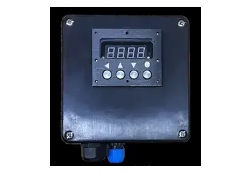
Single-circuit control boxes
For a defined local heating circuit with its required switching and temperature input. Confirm whether the box also contains the incoming isolating and protective devices.
Enquire about this configurationA heat-tracing control panel combines electrical distribution with the switching, temperature controls and monitoring selected for a heating installation.
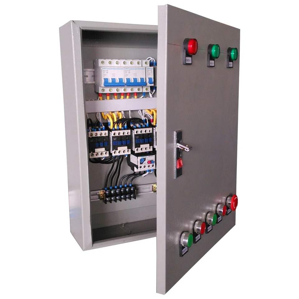
A heat-tracing control panel combines electrical distribution with the switching, temperature controls and monitoring selected for a heating installation. A distribution panel may feed circuits whose controls are located elsewhere; an integrated panel also houses the relevant control functions. One incoming supply can serve several outgoing circuits, but each circuit still needs its own defined load, protection and operating purpose. The panel is specified as an assembly, including its internal components, enclosure, terminals, wiring and documented interfaces with the field equipment.
List every heater, supply and sensing zone, then define switching, protection and operator access so the enclosure contains the functions the installation actually needs.
For a defined local heating circuit with its required switching and temperature input. Confirm whether the box also contains the incoming isolating and protective devices.
Enquire about this configurationFor a group of outgoing heat-tracing circuits supplied from one location. Develop a circuit schedule covering each load, protective device, terminal group and field destination.
Enquire about this configurationFor circuits with separate temperature inputs or operating zones. Map sensors, outputs and alarms so a common enclosure does not obscure the responsibilities of each control loop.
Enquire about this configurationFor installations requesting selected status signals, local indication or remote supervision. Agree the alarm list and interface with the site control system before defining internal components.
Enquire about this configurationDevelop incoming and outgoing arrangements from the actual circuit data. Grouping circuits may help operation, but it should not conceal different startup conditions, temperatures or maintenance requirements.
Discuss mounting, cable bending space, terminal access and enclosure clearances with the installation drawing. Wall-mounted and floor-standing arrangements need different service and support provisions.
Define automatic operation, local intervention, alarm acknowledgement and restart after a supply interruption. State which protective functions remain active during any manual operating mode.
Share these details with your inquiry. Product ratings and operating limits are confirmed for the selected configuration.
| What to specify | Unit / format | Selection guidance |
|---|---|---|
| Incoming electrical supply | V / Hz / phase / A | Provide supply arrangement, available capacity, earthing system and the project's electrical design conditions. |
| Outgoing circuit schedule | circuits / A / kW | List each heating circuit, cable type, operating current, startup demand and required spare provision. |
| Temperature-control zones | zones / sensors / °C | Map setpoints and sensors to outputs, including any shared ambient-control groups. |
| Switching method | type / duty | Identify direct switching, contactor control or a reviewed solid-state arrangement and its switching duty. |
| Protection requirements | device / coordination data | Specify the required circuit protection, residual-current or ground-fault functions and coordination with upstream equipment. |
| Enclosure and installation | mm / environment | Give wall or floor mounting, available space, cable-entry direction and site exposure conditions. |
| Internal thermal conditions | °C / operating duty | State ambient conditions and simultaneous operating loads so component dissipation and enclosure temperature can be assessed. |
| Operator and plant interfaces | signals / protocol | List local controls, indications, remote status points, interlocks and permitted supervisory commands. |
| Documentation and verification | document / test requirement | Identify drawings, terminal schedules, labels and project-specific inspection or test records required for acceptance. |
Provide supply arrangement, available capacity, earthing system and the project's electrical design conditions.
List each heating circuit, cable type, operating current, startup demand and required spare provision.
Map setpoints and sensors to outputs, including any shared ambient-control groups.
Identify direct switching, contactor control or a reviewed solid-state arrangement and its switching duty.
Specify the required circuit protection, residual-current or ground-fault functions and coordination with upstream equipment.
Give wall or floor mounting, available space, cable-entry direction and site exposure conditions.
State ambient conditions and simultaneous operating loads so component dissipation and enclosure temperature can be assessed.
List local controls, indications, remote status points, interlocks and permitted supervisory commands.
Identify drawings, terminal schedules, labels and project-specific inspection or test records required for acceptance.
For multiple pipe-heating circuits serving a building or utility network. Supply the circuit locations and control groups so operators can identify and isolate the correct section.
For installations containing different maintained temperatures and operating schedules. Include the sensor map, critical circuits and plant interface rather than selecting a cabinet by total power alone.
For consolidating or replacing existing circuit controls. Record the installed cables, protection and wiring before deciding which functions can be retained and which interfaces need revision.
Identify every outgoing load, circuit length, supply and sensing requirement. Include cold-start conditions and simultaneous operation instead of relying only on normal running power.
State which sensors, field junctions, protective devices and supervisory functions belong inside the panel package. Agree responsibility for upstream supply and downstream field wiring.
Use the single-line diagram, control sequence and enclosure layout together. Agree document and verification requirements before the configuration becomes the basis for an order.
Send your application details, drawing and planned quantity. We can review the configuration and the information needed for a quotation.
These references explain heating principles. Confirm the ratings, approvals and operating limits of the proposed VELHEAT configuration in its own documentation.
General separation of control, monitoring, sensing and supervisory interfaces; no component ratings or approval claims adopted.