Manual temperature controls
For a straightforward local setpoint with a knob or simple keys. Specify whether the control follows room or floor temperature and whether the installation needs a separate floor limit.
Enquire about this configurationAn underfloor heating thermostat uses a room sensor, a floor probe or a combination of both to regulate an electric heating circuit.
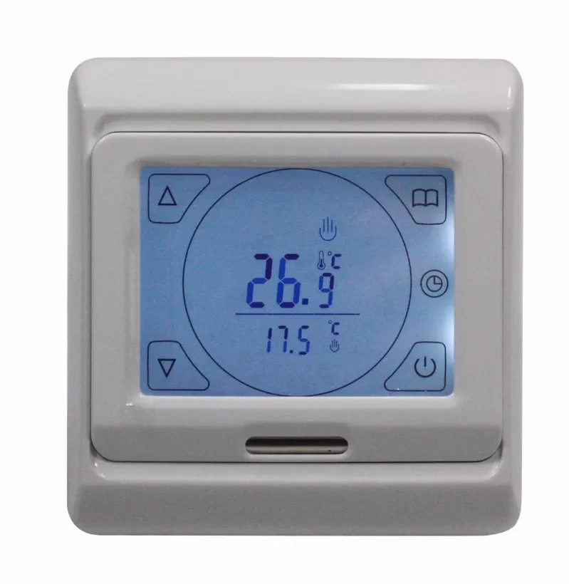
An underfloor heating thermostat uses a room sensor, a floor probe or a combination of both to regulate an electric heating circuit. The thermostat controls the supply to the heating cable or mat; it does not produce the heat. Room control follows the air temperature at the thermostat, while floor control follows the embedded probe. A combined arrangement can regulate room comfort while applying a floor-temperature limit. The useful configuration depends on the floor covering, heating layout and whether the system provides background warmth or contributes to space heating.
Manual, scheduled and connected controls need the right sensor input and electrical interface before their display or remote features can be selected.
For a straightforward local setpoint with a knob or simple keys. Specify whether the control follows room or floor temperature and whether the installation needs a separate floor limit.
Enquire about this configurationFor heating schedules that follow occupancy. Discuss the daily program, temporary override, holiday behavior and the way settings should recover after an interruption to the power supply.
Enquire about this configurationFor a screen-led interface with visible operating modes. Review mounting depth, display language, brightness and access restrictions alongside the required sensor and load connections.
Enquire about this configurationFor projects requesting remote adjustment as well as local operation. Confirm network requirements, account ownership, supported software and the functions that remain available without an internet connection.
Enquire about this configurationTreat the thermostat and embedded floor sensor as a pair. For a replacement, send the existing probe specification and wiring information so the inquiry addresses the installed sensor rather than relying on connector appearance.
Discuss manual adjustment, timed operation and access to advanced settings. Rental properties, staffed facilities and private rooms may need different override and lock arrangements even when their heating circuits are similar.
Identify which rooms share a circuit and where the controlling sensor is located. Larger connected loads may require an external switching assembly; define its coil interface and operating sequence with the electrical designer.
Share these details with your inquiry. Product ratings and operating limits are confirmed for the selected configuration.
| What to specify | Unit / format | Selection guidance |
|---|---|---|
| Heating circuit supply | V / Hz | State the installation voltage and frequency, including any separate supply used by the controller. |
| Connected heating load | W / A | List every mat or cable on the zone and its combined load; identify whether switching is direct or through a contactor. |
| Control and limit temperatures | °C | Give the desired room or floor setpoint and the floor assembly's permitted temperature limit. |
| Floor probe compatibility | Ω / kΩ / °C | Provide the sensor type and resistance-versus-temperature data, especially when retaining an existing probe. |
| Mounting interface | mm | Supply wall-box dimensions, fixing centers, available depth and the permitted faceplate size. |
| Control sequence | mode / schedule | Choose room sensing, floor sensing or room control with a floor limit, together with scheduling and override needs. |
| Location and exposure | environment / °C | Describe the proposed controller location, ambient conditions and relevant wet-area installation constraints. |
| Remote access requirements | network / interface | State whether remote access is required and identify network, account, language and offline-operation expectations. |
State the installation voltage and frequency, including any separate supply used by the controller.
List every mat or cable on the zone and its combined load; identify whether switching is direct or through a contactor.
Give the desired room or floor setpoint and the floor assembly's permitted temperature limit.
Provide the sensor type and resistance-versus-temperature data, especially when retaining an existing probe.
Supply wall-box dimensions, fixing centers, available depth and the permitted faceplate size.
Choose room sensing, floor sensing or room control with a floor limit, together with scheduling and override needs.
Describe the proposed controller location, ambient conditions and relevant wet-area installation constraints.
State whether remote access is required and identify network, account, language and offline-operation expectations.
For electric floor-heating circuits whose controller needs to match the heater load and floor build-up. Include the floor-covering supplier's limits and the heating-system layout in the selection brief.
For rooms with predictable occupied and unoccupied periods. Supply the occupancy pattern and expected warm-up behavior so the proposed schedule is useful for the actual floor construction.
For an existing installation needing a new interface or changed controls. Keep the old wiring diagram, heater rating and probe data together; a matching wall plate alone does not establish compatibility.
Record heater types, electrical load, floor construction and probe position. Separate the required room temperature from the permitted floor temperature before choosing a control mode.
Match supply, switching capacity, sensor characteristics and wall-box dimensions. If the thermostat drives another switching device, include that device's input and the complete control sequence.
Agree how occupants change the temperature, how schedules are overridden and who manages remote access. Include a local operating method and the intended behavior after a power or network interruption.
Send your application details, drawing and planned quantity. We can review the configuration and the information needed for a quotation.
These references explain heating principles. Confirm the ratings, approvals and operating limits of the proposed VELHEAT configuration in its own documentation.
General probe testing and controller load matching; no third-party ratings or warranty adopted.