VELHEAT

Foil Underfloor Heating Mats

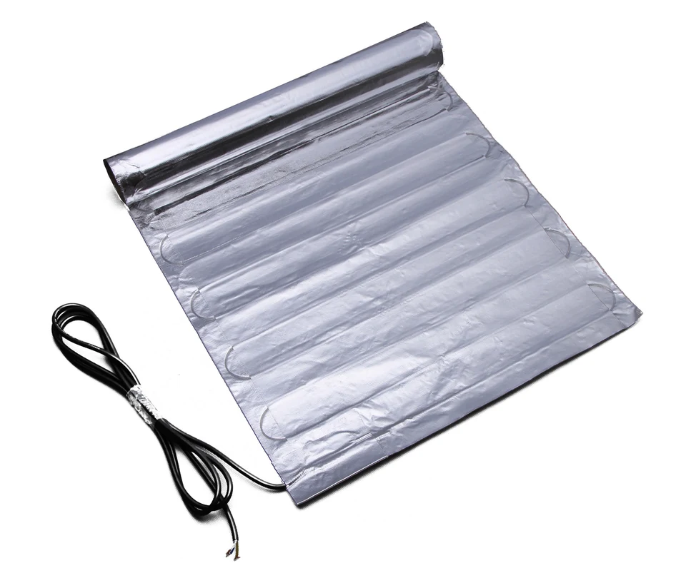
A foil underfloor heating mat contains an insulated resistance-heating cable within an aluminum foil assembly.

Partially rolled foil heating mat with serpentine cable runs and a power lead.
Product reference. Construction and finish follow the agreed specification.

About Foil Underfloor Heating Mats

A foil underfloor heating mat contains an insulated resistance-heating cable within an aluminum foil assembly. The foil spreads heat across the floor area, while the heating circuit provides the electrical input. Its installation belongs to a specified floor build-up: the supporting underlay, protective layers and floor finish all influence heat transfer and mechanical protection. This format is commonly associated with floating laminate and engineered wood. Carpet applications require their own compatible build-up. A foil mat should not inherit the installation instructions of a mesh heating mat embedded in tile adhesive.

For your project, start with the complete floor construction, clear heated area and electrical supply. VELHEAT can discuss the mat layout and connection requirements around those inputs.

Product Configurations

Floating laminate floor mats

For compatible floating laminate systems. Review the locking profile, attached backing and underlay together, then define the mat coverage around fixed furniture and unheated perimeter areas.

Enquire about this configuration

Engineered-wood floor mats

For engineered flooring approved by its supplier for the proposed heating arrangement. Board construction, thickness and permitted surface temperature matter as much as the requested mat dimensions.

Enquire about this configuration

Carpet-system heating mats

For a reviewed carpet and underlay assembly with any necessary protective overlay. Confirm the complete floor detail before selecting a foil mat; a carpet description alone does not establish compatibility.

Enquire about this configuration
Partially rolled foil heating mat with serpentine cable runs and a power lead.

Customize for Your Application

Coverage around the room plan

Discuss mat widths and lengths against the usable floor area. Keep the heating circuit clear of fixed obstructions and choose a layout that reaches the connection point without stretching, overlapping or modifying the heating wire.

Heating and electrical arrangement

Coordinate the requested heat input, available voltage and control zones. Multiple mats need a defined connection arrangement and a load check; sharing a room does not automatically make them suitable for one thermostat output.

Floor-system interfaces

Review the supporting underlay, any protective overlay and the cold-lead transition. Specify how grounding continuity, floor sensing and connection access will be maintained after the floor finish is installed.

Technical Information to Specify

Share these details with your inquiry. Product ratings and operating limits are confirmed for the selected configuration.

What to specifyUnit / formatSelection guidance
Floor finish and installation methodmaterial / build-upProvide the flooring data sheet and identify floating, glued or mechanically fixed construction.
Heated floor aream² / dimensioned planMark the useful heating area, fixed furniture, floor penetrations and excluded zones.
Mat dimensions and layoutmm / quantityShow available strip widths, turns and the route back to the electrical connection.
Floor thermal resistancem²·K/W / togGive the resistance of all layers above the heater, including carpet or attached backing.
Heating requirementW/m² / WState comfort-warming or room-heating duty and provide the room heat-loss calculation where applicable.
Power supply and zone loadV / Hz / AIdentify the local supply, total connected load and thermostat or switching capacity.
Temperature limits°CSupply the flooring manufacturer's maximum permitted temperature and the intended control target.
Leads and floor sensormm / locationLocate the thermostat, cold-lead route and sensor provision within the floor detail.
Room environmentinstallation descriptionIdentify moisture exposure, floor cleaning and the exact room use for compatibility review.
Floor finish and installation method
material / build-up

Provide the flooring data sheet and identify floating, glued or mechanically fixed construction.

Heated floor area
m² / dimensioned plan

Mark the useful heating area, fixed furniture, floor penetrations and excluded zones.

Mat dimensions and layout
mm / quantity

Show available strip widths, turns and the route back to the electrical connection.

Floor thermal resistance
m²·K/W / tog

Give the resistance of all layers above the heater, including carpet or attached backing.

Heating requirement
W/m² / W

State comfort-warming or room-heating duty and provide the room heat-loss calculation where applicable.

Power supply and zone load
V / Hz / A

Identify the local supply, total connected load and thermostat or switching capacity.

Temperature limits
°C

Supply the flooring manufacturer's maximum permitted temperature and the intended control target.

Leads and floor sensor
mm / location

Locate the thermostat, cold-lead route and sensor provision within the floor detail.

Room environment
installation description

Identify moisture exposure, floor cleaning and the exact room use for compatibility review.

Operating Limits to Check

  • Use only within a reviewed floor build-up; generic foil mats are not automatically suitable for tile adhesive, wet rooms or every carpet.
  • Do not overlap mats, cut heating conductors or place the heater under fixed obstructions that conflict with its installation instructions.
  • Floor-temperature limits and electrical protection must follow the selected assembly and applicable installation requirements.

Typical Applications

Floating-floor renovations

For projects replacing a floor finish where the complete proposed construction can accommodate foil heating. Check thresholds, doors and existing substrate condition alongside the heating layout.

Residential rooms with laminate or wood

For floor comfort or a calculated space-heating duty. Identify permanent cabinetry and furniture locations before defining coverage, and assess the floor supplier's temperature restrictions.

Compatible carpeted areas

For a documented carpet system with suitable underlay and protection above the heater where required. Include carpet backing and overlay information in the inquiry so the layers can be assessed together.

How to Select the Right Configuration

Confirm the floor assembly first

Send a section through every proposed floor layer, with the flooring supplier's heating guidance. Resolve material and installation compatibility before choosing output or ordering a nominal room-size mat.

Measure the clear heating area

Use a dimensioned plan that shows exclusions and the thermostat position. Compare candidate mat layouts with the actual free area; the heating cable cannot be shortened to absorb an ordering error.

Coordinate control and handover

Specify the floor sensor and temperature limit, electrical protection and installation checks. Keep the approved layout and test records available for the flooring installer and the person commissioning the system.

Discuss Your Foil floor heating mats Requirement

Send your application details, drawing and planned quantity. We can review the configuration and the information needed for a quotation.

Frequently Asked Questions

A foil mat encloses the heating cable in a foil assembly and is selected for a compatible dry floor build-up. A mesh mat holds cable on an open backing for the specified embedding layer. Their floor interfaces and installation methods differ, even when the electrical outputs look similar.
No. The floor finish, underlay, backing and any protective overlay must work as a complete system. Send their technical data and installation method. A material being described as suitable for underfloor heating does not automatically approve every foil heater or every arrangement of floor layers.
Do not shorten or cut the heating wire. Order the heating circuit to the required area and electrical specification. Where a selected mat permits cutting and turning of the foil carrier, follow its specific procedure and maintain the prescribed grounding connections without damaging or crossing the cable.
That depends on the room heat loss and the usable heated area. The floor's allowable temperature and thermal resistance can limit the useful output. Compare the calculated room demand with the permitted floor-system output before deciding whether additional room heating is needed.
Room air and floor temperature are different measurements. A floor sensor allows a compatible controller to limit the floor condition as well as respond to room demand. Its location and configuration must suit the heating layout and flooring limit; it should not be chosen solely for convenient wiring.
Send the room plan, floor-layer details, supply voltage, heating purpose and desired quantities to info@velheat.com. Add any flooring temperature limits and installation constraints. Mat configuration, order quantity and any sample requirements can then be discussed against the project specification.
Order quantities are agreed for each custom project. Contact VELHEAT with your intended configuration and planned quantity so these can be discussed together.
Technical references

These references explain heating principles. Confirm the ratings, approvals and operating limits of the proposed VELHEAT configuration in its own documentation.

  • Foil Heater System

    General dry-build-up, floating-floor and protective-overlay distinctions; no manufacturer dimensions, ratings or approvals adopted.

  • Foil Heating System Installation Manual

    General relevance of floor-layer compatibility, heating-wire protection and grounding continuity; instructions remain assembly-specific.

WhatsApp