VELHEAT

PTC Heating Plates

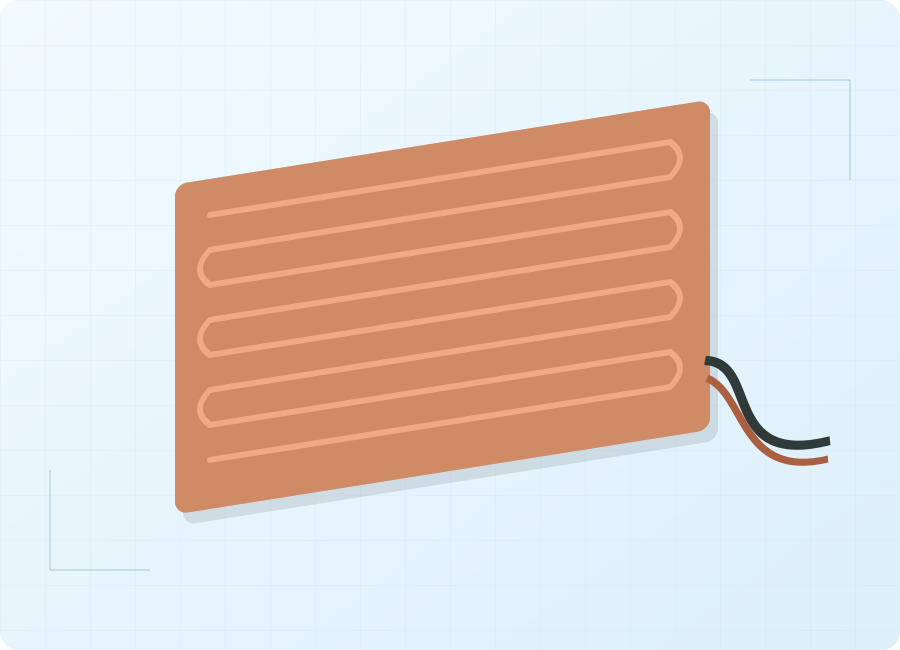
A thick-film PTC heating plate is a flat component with a positive-temperature-coefficient resistive layer.

PTC Heating Plates — conceptual product-form illustration
Product-form illustration. Final construction follows the agreed specification.

About PTC Heating Plates

A thick-film PTC heating plate is a flat component with a positive-temperature-coefficient resistive layer. This construction combines an electrically insulating layer and a heating layer on a metal substrate. In a suitable thermal-management assembly, heat passes from the plate into the intended thermal path, which may include a circulating liquid medium. It is a component-level product, distinct from a finished PTC air heater or fan-assisted cabin heater. Its usable output depends on the electrical input, heat-transfer interface and conditions that carry heat away from the plate.

Start with the required heat path, plate interface and electrical conditions, then assess temperature response and protection in the complete system. Plate output alone does not define the performance of a coolant heater.

Product Configurations

Battery thermal-management plates

For integration into a defined battery-heating thermal path. Specify whether heat is transferred through a coolant assembly or another interface, along with the battery system's temperature and control requirements.

Enquire about this configuration

Cabin-heating coolant interfaces

For a plate considered as part of a liquid-mediated cabin-heating assembly. Define the heat-exchanger interface and operating states; a heating plate is not a complete cabin heater.

Enquire about this configuration

Integrated thermal-management layouts

For equipment coordinating several thermal demands. Identify the actual circuit receiving heat, its flow conditions and control responsibility so the plate is evaluated within a clearly defined assembly.

Enquire about this configuration
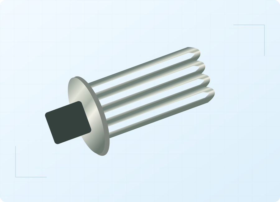
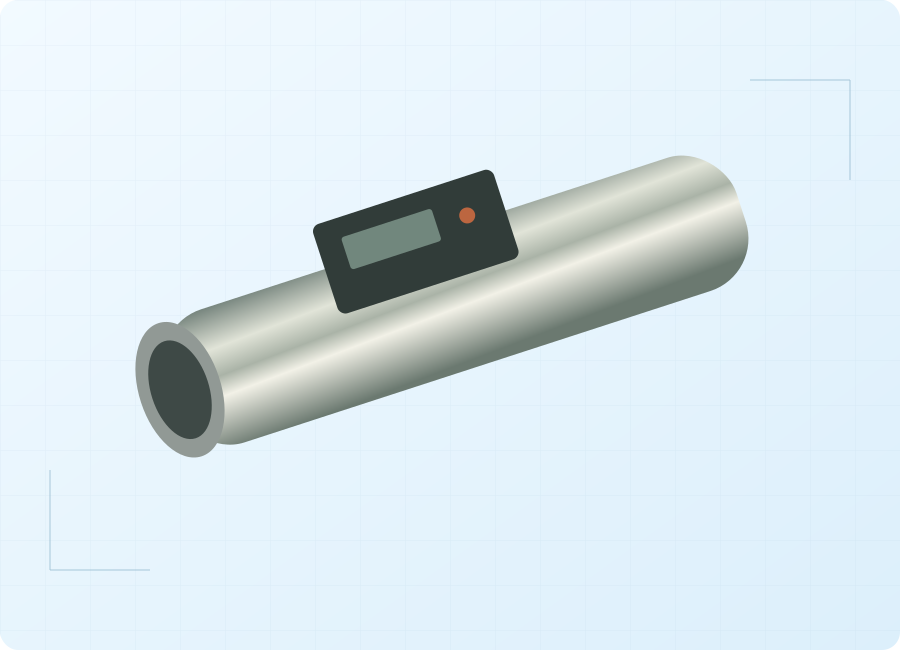
PTC Heating Plates — conceptual product-form illustration

Customize for Your Application

Plate-to-system interface

Review the useful heat-transfer area and the structure receiving the heat. Distinguish the plate component from coolant passages, seals and other parts of the finished assembly.

Electrical behavior

Discuss the resistance and power response across the required temperature and supply envelope. Establish the conditions used to compare startup performance and steady operation.

Mounting and expansion

Coordinate the mounting layout with the surrounding structure and operating cycle. Include mechanical support and interface consistency in the drawing review instead of relying only on overall plate dimensions.

Validation plan

Define the measurements needed on a representative assembly: useful heat transfer, temperature distribution, electrical isolation and behavior under relevant fault conditions. Keep acceptance criteria tied to equipment requirements.

Technical Information to Specify

Share these details with your inquiry. Product ratings and operating limits are confirmed for the selected configuration.

What to specifyUnit / formatSelection guidance
Plate envelope and interfacemmProvide outline, thickness allowance, mounting areas and the useful heat-transfer face on a controlled drawing.
Electrical operating envelopeV / AState nominal supply, variation, startup conditions and the equipment's current or power constraints.
Required heat inputW / W/cm²Define output at specified thermal-interface conditions rather than treating maximum power density as a universal operating point.
Temperature-response requirement°C / ΩSpecify the operating temperature objectives and the resistance-temperature data needed for system design.
Heat-removal conditionsL/min / °CFor liquid-mediated assemblies, provide fluid composition, flow range and inlet temperature at relevant operating cases.
Electrical isolationtest requirementState dielectric, insulation and system-isolation acceptance requirements for the complete assembly.
Mechanical and thermal cyclingcycle / profileProvide the operating cycle, vibration environment and required assembly-level validation conditions.
Terminations and controltype / signalDefine connection access, sensing, power regulation and the required response to loss of heat removal.
Plate envelope and interface
mm

Provide outline, thickness allowance, mounting areas and the useful heat-transfer face on a controlled drawing.

Electrical operating envelope
V / A

State nominal supply, variation, startup conditions and the equipment's current or power constraints.

Required heat input
W / W/cm²

Define output at specified thermal-interface conditions rather than treating maximum power density as a universal operating point.

Temperature-response requirement
°C / Ω

Specify the operating temperature objectives and the resistance-temperature data needed for system design.

Heat-removal conditions
L/min / °C

For liquid-mediated assemblies, provide fluid composition, flow range and inlet temperature at relevant operating cases.

Electrical isolation
test requirement

State dielectric, insulation and system-isolation acceptance requirements for the complete assembly.

Mechanical and thermal cycling
cycle / profile

Provide the operating cycle, vibration environment and required assembly-level validation conditions.

Terminations and control
type / signal

Define connection access, sensing, power regulation and the required response to loss of heat removal.

Operating Limits to Check

  • PTC material behavior does not replace assembly-level temperature, flow or electrical protection.
  • A heating plate does not establish the pressure rating or liquid compatibility of a complete coolant heater.
  • Automotive qualification, service life and vehicle-range improvements require relevant validation evidence.

Typical Applications

Battery-system coolant heating

For an integrated thermal-management concept that transfers heat through a liquid medium. The battery-system design establishes operating limits and control permissions; the plate is evaluated within that architecture.

Vehicle cabin heat support

For a suitable coolant-based cabin-heating assembly. Define the required useful heat and fluid conditions, with the air-side heat exchanger and vehicle control system treated as separate integration responsibilities.

Shared vehicle thermal circuits

For a system that distributes heat to defined vehicle subsystems. Identify the valve and pump states that affect the plate's thermal path before assessing the component's operating envelope.

How to Select the Right Configuration

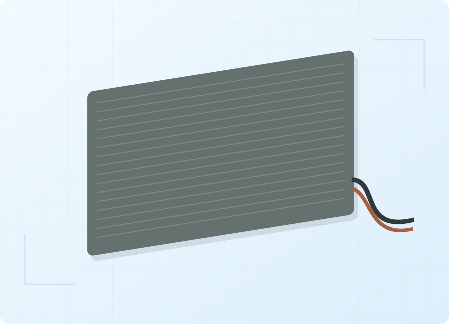
Define the component boundary

Identify what is being purchased: the plate, a mounted subassembly or a complete liquid-heating unit. Provide an interface drawing and allocate responsibility for fluid containment, controls and protection.

Specify representative conditions

Set the electrical supply and heat-removal conditions for each required output point. Include cold startup and reduced circulation so nominal plate power is not mistaken for a complete system rating.

Validate the assembled thermal path

Agree a test plan using the intended interface and controls. Compare temperature distribution, electrical behavior and useful heat under the defined conditions, then review relevant abnormal operating states.

Discuss Your PTC heating plates Requirement

Send your application details, drawing and planned quantity. We can review the configuration and the information needed for a quotation.

Frequently Asked Questions

No. A plate can provide heat within a liquid-heating assembly, but fluid passages, containment, seals, sensors and controls are additional design elements. Establish the supply boundary on a drawing. The rating or material description of the plate alone does not establish the pressure or performance rating of the finished unit.
A plate presents a defined heat-transfer surface for integration into an assembly. A finished air heater uses a different thermal path and typically includes structures designed to exchange heat with moving air. A shared PTC description does not make those products mechanically, electrically or thermally interchangeable.
PTC describes increasing electrical resistance with temperature over the relevant response region. The resulting operating point also depends on supply and heat removal. An exact system temperature still requires a defined control and measurement strategy. Request the response data and evaluate it in the intended assembly instead of assuming a universal fixed setpoint.
Use the same supply, contact arrangement, heat-removal conditions and acceptance limits for each comparison. Include the required electrical-isolation and durability evidence. Comparing headline power density or substrate thickness alone can conceal differences in the test setup and does not establish useful heating performance in your equipment.
Order quantities are agreed for each custom project. Contact VELHEAT with your intended configuration and planned quantity so these can be discussed together.
Technical references

These references explain heating principles. Confirm the ratings, approvals and operating limits of the proposed VELHEAT configuration in its own documentation.

WhatsApp