Assembled insertion probes
For a defined process measurement point using a protective tube and connection head. Specify the required insertion, process connection and arrangement for access or replacement.
Enquire about this configurationAn RTD, or resistance temperature detector, measures temperature through the change in electrical resistance of its sensing element.
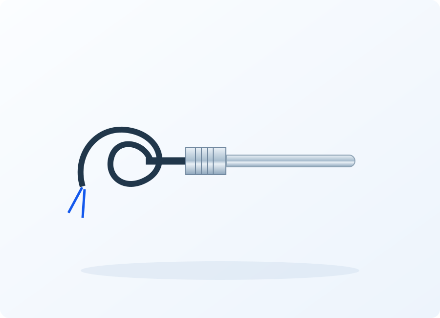
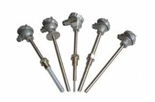
An RTD, or resistance temperature detector, measures temperature through the change in electrical resistance of its sensing element. A platinum RTD is often identified by a designation such as Pt100, but that name alone does not specify the complete probe. The element characteristic, wiring, protective construction, insertion depth and connection all affect the installed measurement. An RTD supplies temperature information to a compatible instrument; it is not a heating element or a device that switches heater power by itself.
Match the element and wiring to the controller, then define the probe, mounting connection and exposure so the measured temperature is useful to the heating process.
For a defined process measurement point using a protective tube and connection head. Specify the required insertion, process connection and arrangement for access or replacement.
Enquire about this configurationFor applications needing a compact protected sensing assembly. Discuss sheath diameter, length, routing and connection style against the selected construction and measurement duty.
Enquire about this configurationFor one measurement channel or two sensing elements within an agreed assembly. Define how the channels are used and whether separate protection functions require additional independence.
Enquire about this configurationFor defined measurement locations within a reviewed process arrangement. Provide each sensing position and operating condition; the suitability of a multipoint assembly depends on the actual process and construction.
Enquire about this configurationUse the equipment drawing to establish insertion, mounting and service access. Where a thermowell is already installed, provide its internal dimensions and intended sensor engagement rather than only the external connection size.
Discuss element characteristic, wire count and cable route with the receiving instrument. Any transmitter or signal conversion should be identified separately so a direct resistance input is not confused with an electrical current signal.
State which measurement points matter to the process and what records the project requires. Sensor tolerance and installed system accuracy are different requirements; the latter also includes leads, input electronics and placement.
Share these details with your inquiry. Product ratings and operating limits are confirmed for the selected configuration.
| What to specify | Unit / format | Selection guidance |
|---|---|---|
| Sensor element characteristic | type / Ω | State the platinum element designation, resistance characteristic and compatible instrument input. |
| Measurement and exposure | °C | Separate the normal measurement range from maximum process exposure and connection-head ambient temperature. |
| Wiring configuration | 2 / 3 / 4 wires | Match the lead arrangement to the instrument and account for the installed lead resistance. |
| Required measurement performance | °C / tolerance requirement | Define allowable system error and the temperature points at which verification is needed. |
| Probe geometry | mm | Provide sheath or protection-tube diameter, total length, insertion length and any permitted routing constraints. |
| Process connection | thread / flange / drawing | Identify the mounting interface, seal arrangement and any existing thermowell or protective fitting. |
| Medium and mechanical conditions | bar / flow / composition | Describe pressure, flow, chemistry, vibration and cleaning that affect the complete installed assembly. |
| Lead and termination | m / terminal type | Specify lead length, insulation environment, connection head or connector and the route to the instrument. |
| Response and sensing position | s / mm | State the required response with its test conditions and locate the sensing element relative to the process. |
State the platinum element designation, resistance characteristic and compatible instrument input.
Separate the normal measurement range from maximum process exposure and connection-head ambient temperature.
Match the lead arrangement to the instrument and account for the installed lead resistance.
Define allowable system error and the temperature points at which verification is needed.
Provide sheath or protection-tube diameter, total length, insertion length and any permitted routing constraints.
Identify the mounting interface, seal arrangement and any existing thermowell or protective fitting.
Describe pressure, flow, chemistry, vibration and cleaning that affect the complete installed assembly.
Specify lead length, insulation environment, connection head or connector and the route to the instrument.
State the required response with its test conditions and locate the sensing element relative to the process.
For control systems that need a measured pipe, equipment or ambient condition. Define a suitable sensing assembly and mounting position with the heat-tracing design rather than selecting by element designation alone.
For temperature monitoring at a defined insertion point. Include pressure, fluid chemistry and protective fittings so mechanical suitability is evaluated alongside the electrical measurement.
For an existing instrument input or probe interface. Supply the original drawing, connection details and sensor characteristic to avoid replacing a mechanically similar probe with an incompatible electrical element.
Identify whether the control needs surface, ambient or process-fluid temperature. Review gradients and installation access before setting the sensing location and probe geometry.
Check the element characteristic, number of leads and receiving instrument. Record cable length and routing, together with any junctions or signal conversion between the probe and controller.
Assess probe materials, process connection, protective fittings and the required verification record. Treat pressure and hazardous-location requirements as properties of an evaluated installation, not of the sensing element alone.
Send your application details, drawing and planned quantity. We can review the configuration and the information needed for a quotation.
These references explain heating principles. Confirm the ratings, approvals and operating limits of the proposed VELHEAT configuration in its own documentation.
General two-, three- and four-wire measurement and lead-resistance compensation; no instrument performance adopted.