VELHEAT

Heat-Tracing Connection & Termination Kits

Heat-tracing connection kits provide the electrical connection and environmental sealing needed at defined points in a heating circuit.

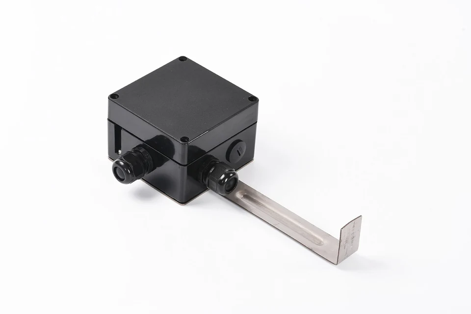
Black junction box with cable glands and a metal pipe-mounting bracket.
Product reference. Construction and finish follow the agreed specification.

About Heat-Tracing Connection & Termination Kits

Heat-tracing connection kits provide the electrical connection and environmental sealing needed at defined points in a heating circuit. A power connection brings the supply to the cable; an inline joint connects compatible sections; a tee serves an approved branch arrangement; an end seal isolates the free cable end. Some designs use an accessible junction box above the insulation, while the detailed cable entry and sealing components depend on the cable construction. A generic enclosure and a complete cable connection kit are not interchangeable descriptions.

Identify the power entry, joints, branches and ends, then specify compatible sealing, terminals and mounting so every connection has a defined function.

Product Configurations

Power connection assemblies

For the transition from supply conductors to a compatible heating cable. Define the supply entry, heating-cable entries, terminals, protective-conductor connection and mounting arrangement.

Enquire about this configuration

Inline and two-way connections

For joining compatible heating-cable sections where the system design permits it. Match both cable ends and include the connection's electrical, sealing and mechanical requirements.

Enquire about this configuration

Tee and three-way connections

For an approved branch point in a suitable circuit design. Review the complete branched load, connection arrangement and cable-specific rules before specifying the component.

Enquire about this configuration

End termination assemblies

For sealing the free end of the designated cable. Specify the cable construction and installation position, including whether the termination remains accessible above the thermal insulation.

Enquire about this configuration

Lighted end and power connections

For local indication at the selected connection point. Match the indicator's electrical supply and define what its illumination represents within the circuit monitoring strategy.

Enquire about this configuration

Cable-entry and connection components

For the compatible glands, seals, insulating parts and terminal arrangements required by a defined assembly. Confirm the complete bill of materials rather than assuming every enclosure includes them.

Enquire about this configuration
Black junction box with cable glands and a metal pipe-mounting bracket.

Customize for Your Application

A connection schedule for the circuit

Count components from the actual routing and branch drawing. A circuit may need several different connection functions, and the correct quantity of end seals depends on its permitted topology.

Enclosure and support arrangement

Discuss the mounting base or backplate, entry directions and the stand-off above insulation. Coordinate the support with the pipe and cladding details so the connection remains reachable without straining the cable.

An explicit component list

Define what comes with each assembly and what is supplied separately. Cable-specific connection parts, support straps and end seals should appear in the agreed list rather than being assumed from a photograph.

Technical Information to Specify

Share these details with your inquiry. Product ratings and operating limits are confirmed for the selected configuration.

What to specifyUnit / formatSelection guidance
Heating cable identificationconstruction / drawingProvide the cable specification, dimensions, jacket material, braid or sheath and conductor arrangement.
Connection functionpower / joint / branch / endMark each component on the circuit drawing and state the number and direction of cable entries.
Electrical dutyV / A / conductor sizeState supply, operating and startup conditions, supply conductor size and required terminal arrangement.
Operating environment°C / exposureDescribe pipe and ambient temperatures, moisture, chemicals, UV exposure and mechanical conditions.
Mounting and insulationmmProvide pipe diameter, insulation thickness, cladding position and available installation clearance.
Entry and sealing interfacethread / cable dimensionsIdentify gland threads, cable profiles and the specified sealing method for the complete assembly.
Access and inspectionlocation / procedureState whether the connection must remain accessible and define the project inspection and test requirements.
Indicator requirementV / functionFor a lighted connection, specify the supply and the indication required at that exact point.
Kit scopebill of materialsConfirm enclosure, stand, clamps, entry components, terminals, seals and end-termination materials individually.
Heating cable identification
construction / drawing

Provide the cable specification, dimensions, jacket material, braid or sheath and conductor arrangement.

Connection function
power / joint / branch / end

Mark each component on the circuit drawing and state the number and direction of cable entries.

Electrical duty
V / A / conductor size

State supply, operating and startup conditions, supply conductor size and required terminal arrangement.

Operating environment
°C / exposure

Describe pipe and ambient temperatures, moisture, chemicals, UV exposure and mechanical conditions.

Mounting and insulation
mm

Provide pipe diameter, insulation thickness, cladding position and available installation clearance.

Entry and sealing interface
thread / cable dimensions

Identify gland threads, cable profiles and the specified sealing method for the complete assembly.

Access and inspection
location / procedure

State whether the connection must remain accessible and define the project inspection and test requirements.

Indicator requirement
V / function

For a lighted connection, specify the supply and the indication required at that exact point.

Kit scope
bill of materials

Confirm enclosure, stand, clamps, entry components, terminals, seals and end-termination materials individually.

Operating Limits to Check

  • Connection compatibility must be established for the exact cable and complete assembly.
  • A component enclosure or marking alone does not establish the approval of the installed system.
  • An indicator light is not a substitute for temperature feedback or circuit verification.

Typical Applications

Pipe heat-tracing power entries

For introducing supply power to a specified cable circuit on a pipe or vessel. Include the incoming cable route and protective-conductor arrangement in the connection review.

Permitted joints and branch points

For installations whose selected cable system allows the proposed connection. Review circuit length and electrical loading with the branch arrangement before choosing a junction component.

Accessible circuit terminations

For end points that need a defined sealing and inspection arrangement. Lighted versions can support local status checks when their supply and indication function are specified.

How to Select the Right Configuration

Identify the cable before the box

Obtain the cable's construction and connection requirements. An enclosure that accepts the cable physically may still lack the correct seals, insulating components or terminals.

Check the complete circuit layout

Mark power entries, joints, branches and ends on one drawing. Confirm that the selected cable design permits each connection and that the assembled circuit meets its electrical limits.

Confirm mounting and kit contents

Review stand height, insulation clearance and access alongside the bill of materials. Agree the installation instructions and verification requirements for the complete matched assembly.

Discuss Your Connection & termination kits Requirement

Send your application details, drawing and planned quantity. We can review the configuration and the information needed for a quotation.

Frequently Asked Questions

No. Cable dimensions, insulation, braid or sheath, conductor arrangement and sealing method can differ. Select the kit against the exact cable specification and the required connection function rather than treating similar-looking cables as interchangeable.
The box alone does not permit branching. The selected cable system and electrical design must allow the proposed arrangement. Series-resistance and parallel heating circuits have different connection requirements, so the full layout needs review.
No. A voltage-indicating end light shows the specified electrical condition at its connection point. It does not measure pipe temperature or confirm useful heating along the entire circuit. Temperature and circuit checks serve separate purposes.
That depends on the agreed kit scope. Some assemblies require separate cable-entry components, support straps or termination materials. Review the itemized list for the selected cable and mounting arrangement before placing the order.
Use the termination method specified for the selected cable system. An end seal has defined electrical insulation and environmental sealing responsibilities that should not be replaced by a general-purpose wrapping material.
Send the heating-cable specification, circuit drawing, supply data, insulation thickness and installation environment to info@velheat.com. Mark the required power, joint, branch and end locations, and identify any indicator or access requirements.
Order quantities are agreed for each custom project. Contact VELHEAT with your intended configuration and planned quantity so these can be discussed together.
Technical references

These references explain heating principles. Confirm the ratings, approvals and operating limits of the proposed VELHEAT configuration in its own documentation.

WhatsApp