VELHEAT

Heat-Tracing Temperature Controllers

A heat-tracing temperature controller receives temperature information and switches or regulates a heating circuit.

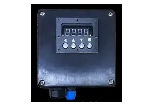
Digital temperature controller in a black enclosure with two cable entries.
Product reference. Construction and finish follow the agreed specification.

About Heat-Tracing Temperature Controllers

A heat-tracing temperature controller receives temperature information and switches or regulates a heating circuit. A mechanical thermostat can use a remotely positioned sensing bulb, while an electronic controller receives an electrical sensor signal and can provide a display or alarms. Ambient sensing responds to surrounding air and can serve freeze-protection duties. Line sensing follows the pipe or equipment temperature and is relevant when the maintained process temperature needs direct feedback. The controller, sensor and power-switching device form one control chain; none should be selected in isolation.

Define ambient or pipe sensing, the heating load and the required response to an abnormal reading, then select the control interface and monitoring functions.

Product Configurations

Mechanical remote-bulb thermostats

For local temperature switching using a sensing bulb and capillary arrangement. Define the sensing location, capillary route, switching load and permitted enclosure location together.

Enquire about this configuration

Digital local controllers

For a visible temperature reading and adjustable control settings. Match the sensor input, output type and required control behavior to the heating circuit and process.

Enquire about this configuration

Controllers with circuit monitoring

For applications requesting temperature status together with selected electrical measurements and alarms. Identify which quantities must be measured and how alarm conditions should be reported.

Enquire about this configuration

Remote supervisory interfaces

For transferring selected operating values or alarms to an existing supervisory system. Define the protocol, point list, command permissions and local fallback before choosing a connected configuration.

Enquire about this configuration
Digital temperature controller in a black enclosure with two cable entries.

Customize for Your Application

Sensing and switching configuration

Map each sensor to its heating zone and output. A pipe network with different flow paths or thermal conditions may require more than one controlled circuit even when a common ambient sensor is suitable elsewhere.

Alarms that support action

State what an operator should do when an alarm occurs. Distinguish a warning from a protective shutdown and describe how acknowledgement, reset and restart should work.

Integration with existing equipment

Provide the panel diagram and supervisory point list for retrofit work. Agree which device owns the temperature setpoint and which control functions remain local if the remote system is unavailable.

Startup current-management options

Where a self-regulating circuit needs a compatible startup-current limiter, review the heater, switching method, startup sequence and bypass arrangement together. A limiter manages startup loading; it does not replace temperature control, circuit protection or cable-length verification.

Technical Information to Specify

Share these details with your inquiry. Product ratings and operating limits are confirmed for the selected configuration.

What to specifyUnit / formatSelection guidance
Control objectiveduty / °CIdentify freeze protection or process maintenance, the desired temperature and allowable variation.
Sensing locationambient / surface / processSpecify what temperature will be measured and where the sensor or bulb is mounted.
Sensor inputtype / wires / ΩProvide the sensor characteristic, wiring arrangement and lead length; identify a mechanical bulb when applicable.
Heating circuit loadV / A / phaseState operating and startup conditions, the cable type and whether the controller switches the load directly.
Power-switching interfacecontact / signalDefine the contactor or solid-state switching interface and any external enable or shutdown input.
Ambient and exposure conditions°C / site descriptionInclude enclosure ambient, condensation, corrosion and the equipment location relative to insulation.
Alarm and fault behaviorcondition / actionList high or low temperature, sensor faults and any electrical alarms with their required responses.
Communications and supervisionprotocol / point listProvide the supervisory interface, monitored values, permitted remote commands and loss-of-communication behavior.
Control objective
duty / °C

Identify freeze protection or process maintenance, the desired temperature and allowable variation.

Sensing location
ambient / surface / process

Specify what temperature will be measured and where the sensor or bulb is mounted.

Sensor input
type / wires / Ω

Provide the sensor characteristic, wiring arrangement and lead length; identify a mechanical bulb when applicable.

Heating circuit load
V / A / phase

State operating and startup conditions, the cable type and whether the controller switches the load directly.

Power-switching interface
contact / signal

Define the contactor or solid-state switching interface and any external enable or shutdown input.

Ambient and exposure conditions
°C / site description

Include enclosure ambient, condensation, corrosion and the equipment location relative to insulation.

Alarm and fault behavior
condition / action

List high or low temperature, sensor faults and any electrical alarms with their required responses.

Communications and supervision
protocol / point list

Provide the supervisory interface, monitored values, permitted remote commands and loss-of-communication behavior.

Operating Limits to Check

  • A controller's normal regulation function does not establish an independent protective limit.
  • Hazardous-location suitability requires assessment of the selected complete equipment and installation.
  • Monitoring functions and communication protocols must be confirmed for the agreed configuration.

Typical Applications

Pipe freeze-protection controls

For heating circuits intended to offset cold-weather pipe losses. Include the exposed sections, minimum ambient condition and whether multiple pipes genuinely share the same control requirement.

Process temperature maintenance

For pipelines or vessels that need feedback from the heated surface or process. Identify thermal differences along the installation and the consequence of a temperature outside the required band.

Monitored heat-tracing circuits

For installations where operations staff need circuit status and diagnostic information. Define alarm reporting and maintenance access so the selected monitoring functions support a clear operating procedure.

How to Select the Right Configuration

Choose the measured condition

Determine whether ambient temperature is an adequate basis for control or whether the pipe or process needs direct measurement. Draw the sensor location and the circuit it controls.

Match every interface

Check the sensor, controller supply, switching output and heating load as a complete chain. Include cold-start current and the thermal conditions around external power-switching components.

Agree the abnormal-condition response

Document the response to an open sensor, lost communication, low temperature and any required high-temperature limit. Define protective functions separately from routine regulation.

Discuss Your Heat-tracing controllers Requirement

Send your application details, drawing and planned quantity. We can review the configuration and the information needed for a quotation.

Frequently Asked Questions

Self-regulation changes the cable's local output with temperature; it does not define the complete system's operating schedule or alarm strategy. A controller may be needed for the specified process, energy management or monitoring duty. Selection should follow the application and the cable system's requirements.
Use the required controlled condition as the starting point. Ambient sensing can respond to weather-related freeze risk, while pipe sensing measures the heated installation more directly. A process with a narrow maintenance requirement or changing operating conditions needs a specific sensing review.
Only when its output and the complete load are compatible under the required operating conditions. Consider startup current and switching duty as well as normal current. Otherwise the controller can operate a separately selected switching device within the control panel.
Not automatically. Routine regulation and protective limiting have different responsibilities. Where the design requires an independent limit, define its sensor, trip action and reset behavior separately rather than assuming the normal controller provides that function.
That depends on the agreed control architecture. Specify which actions remain local and how the circuit behaves when communication is lost. Remote status reporting alone does not establish permission to change setpoints or restart equipment.
Send the heating-cable information, circuit load, sensor requirements, temperature targets and a control diagram to info@velheat.com. Include alarms, site conditions and any supervisory point list so the proposal addresses the complete control duty.
Order quantities are agreed for each custom project. Contact VELHEAT with your intended configuration and planned quantity so these can be discussed together.
Technical references

These references explain heating principles. Confirm the ratings, approvals and operating limits of the proposed VELHEAT configuration in its own documentation.

WhatsApp