VELHEAT

Skin-Effect Heat Tracing Systems

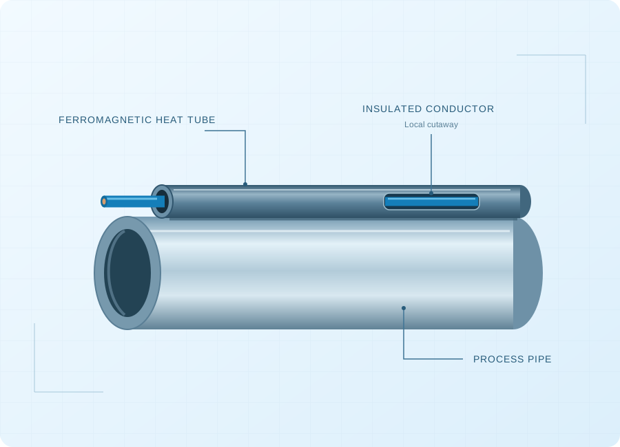
A skin-effect heat tracing system uses an insulated conductor installed inside a ferromagnetic heat tube associated with the carrier pipeline.

Skin-effect system concept: a process pipe, an axial ferromagnetic heat tube and an insulated conductor inside the heat tube
System concept. Electrical connections, insulation and controls are not shown.

About Skin-Effect Heat Tracing Systems

A skin-effect heat tracing system uses an insulated conductor installed inside a ferromagnetic heat tube associated with the carrier pipeline. Alternating current travels through the conductor and returns through the heat tube; skin and proximity effects concentrate the return current toward the tube's inner region. Heat is transferred through the system's designed thermal path to the pipeline. The arrangement is used for engineered long-route heating duties. It requires coordinated electrical, thermal and mechanical design, including insulation, power equipment, terminations, monitoring and the installation interfaces along the route.

Begin with the fluid, route, heat loss and available power locations, then coordinate the heat tube, internal conductor, supply equipment and controls. Cable length alone does not establish a suitable system design.

Product Configurations

Complete long-pipeline heating system

An engineered assembly of heat tube, internal conductor, supply equipment and controls, coordinated with the carrier pipe and insulation. Its dimensions and circuit arrangement follow the route and thermal duty.

Enquire about this configuration

System-matched internal conductor

The insulated conductor is a component of the defined skin-effect circuit. Specify it against the system drawings and electrical design; a generic cable substitution does not establish equivalent performance.

Enquire about this configuration
Skin-effect system concept: a process pipe, an axial ferromagnetic heat tube and an insulated conductor inside the heat tube

Customize for Your Application

Thermal duty definition

Separate normal temperature maintenance from initial warm-up or restart after a shutdown; they may impose different system requirements.

Power-center planning

Review how route length, available supplies and operational sections affect power equipment and circuit division.

Pipeline integration

Coordinate heat-tube installation, pipe supports, expansion, insulation and field joints within the pipeline construction package.

Control and documentation scope

Define the system drawings, interface schedule, monitoring requirements and commissioning records expected for the project.

Technical Information to Specify

Share these details with your inquiry. Product ratings and operating limits are confirmed for the selected configuration.

What to specifyUnit / formatSelection guidance
Pipeline and routemm / km / drawingProvide pipe dimensions, route profile, branches, crossings and the planned insulation and support arrangement.
Fluid and operating modeproperties / flowIdentify the transported material, flow conditions, shutdown duty and the temperature needed for the process.
Thermal design conditions°C / W/mDefine maintain temperature, startup requirements, maximum exposure and heat loss for the actual route conditions.
Heat-tube interfacematerial / drawingCoordinate tube geometry, thermal attachment and installation interfaces with the carrier-pipe design.
Power accessV / phase / locationIdentify available supplies, substations or power-center locations and restrictions on site electrical infrastructure.
Circuit architectureroute / sectionsEstablish circuit lengths and sections through the complete electrical and thermal design rather than a catalogue distance claim.
Control and protectionsignals / schemeSpecify temperature measurement, operating modes, alarms and the plant monitoring interfaces required by the project.
Project environmentclassification / conditionsDeclare hazardous-area requirements, corrosion exposure, ambient conditions and inspection access along the route.
Pipeline and route
mm / km / drawing

Provide pipe dimensions, route profile, branches, crossings and the planned insulation and support arrangement.

Fluid and operating mode
properties / flow

Identify the transported material, flow conditions, shutdown duty and the temperature needed for the process.

Thermal design conditions
°C / W/m

Define maintain temperature, startup requirements, maximum exposure and heat loss for the actual route conditions.

Heat-tube interface
material / drawing

Coordinate tube geometry, thermal attachment and installation interfaces with the carrier-pipe design.

Power access
V / phase / location

Identify available supplies, substations or power-center locations and restrictions on site electrical infrastructure.

Circuit architecture
route / sections

Establish circuit lengths and sections through the complete electrical and thermal design rather than a catalogue distance claim.

Control and protection
signals / scheme

Specify temperature measurement, operating modes, alarms and the plant monitoring interfaces required by the project.

Project environment
classification / conditions

Declare hazardous-area requirements, corrosion exposure, ambient conditions and inspection access along the route.

Operating Limits to Check

  • Circuit distance, supply requirements and maintain temperature are project-specific system results.
  • Descriptions of current distribution do not replace electrical protection, bonding or safe work procedures.
  • A conductor-only purchase is not a complete skin-effect heating system.

Typical Applications

Long transfer pipelines

Skin-effect heating can be considered for extended routes needing temperature maintenance. The design follows the fluid requirement, route heat loss and location of practical electrical feeds.

Viscous-product transfer

A process may require a controlled transport temperature to support the specified fluid behaviour. Product properties and shutdown requirements should define the heating duty before system selection.

Pipeline freeze protection

For a suitable long-route project, protection against freezing becomes a system-level thermal task. Evaluate the full operating and standby conditions, insulation arrangement and monitoring needs.

How to Select the Right Configuration

Build the pipeline design basis

Assemble the route, fluid properties, operating modes and environmental conditions. Establish the required temperature and heat-loss model before deciding the heating-system architecture.

Coordinate the electrical and mechanical system

Review heat tube, conductor, power equipment and pipe interfaces together. Consider construction access and testing boundaries alongside the calculated heating duty.

Define package responsibilities

Document who supplies and installs each component, including insulation and site power. Agree design reviews, inspection records and commissioning requirements across the involved project teams.

Discuss Your Skin-Effect Heat Tracing Requirement

Send your application details, drawing and planned quantity. We can review the configuration and the information needed for a quotation.

Frequently Asked Questions

No. The conductor operates inside a ferromagnetic heat tube as part of a specific AC circuit. The heat tube and its thermal relationship with the carrier pipe are essential. Supply equipment, insulation, terminations and controls also belong to the design. Specifying only a cable length leaves major system requirements undefined.
The permissible length depends on the complete electrical and thermal design, including conductor, heat tube, required output and supply arrangement. A distance advertised for another manufacturer's system is not a general limit or a project guarantee. Provide the route and design duty so circuit division can be established for that installation.
Thermal insulation remains part of the pipeline heating design. Its type, thickness, condition and weather protection influence heat loss and required electrical input. The heat source and insulation should be specified together, including field joints and supports that can affect the thermal behaviour of the installed pipeline.
That must be checked rather than assumed. Maintaining an already warm flowing product and raising a cold pipeline to operating condition are different duties. State the initial condition, fluid properties and required startup behaviour. The system designer can then assess whether one arrangement meets both requirements.
Define the design basis and responsibility boundaries as well as the equipment list. The package should coordinate the heat tube, conductor, electrical supply equipment, connections, controls and monitoring with pipeline insulation and construction. Include the drawings, inspections and commissioning evidence required to accept the installed system.
Order quantities are agreed for each custom project. Contact VELHEAT with your intended configuration and planned quantity so these can be discussed together.
Technical references

These references explain heating principles. Confirm the ratings, approvals and operating limits of the proposed VELHEAT configuration in its own documentation.

WhatsApp